Installation Tips for Hireko's Golf Club Counterweights
Counterweighting golf clubs may greatly improve your game.
For the past 5 years, Hireko has sold an assortment of counterweights for steel and graphite shafts as well as steel putter shafts. There are a number of reasons to counterweight such as moving the balance point of the club closer to the player’s hands to help increase swing speed, helping delay the release of the club and even to help square the face up at impact rather the watching the ball fade or slice away from the target.
In other cases counterweighting can help reduce head heaviness when building longer-than-normal length clubs or create a putter promoting more of a pendulum stroke. So counterweights are a staple for any clubmaking operation and as such we want to point out some installation tips.
 Anatomy of a counterweight
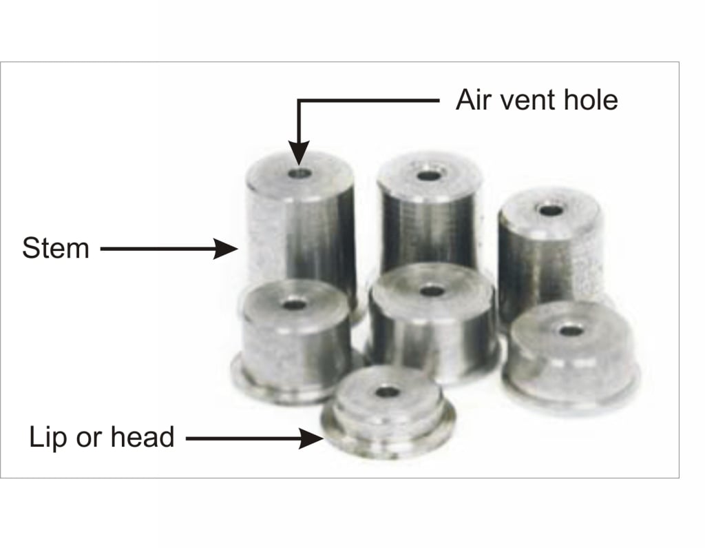
First, here is a quick primer on the anatomy of the counterweights. There are three parts to the counterweight. The stem is the portion that goes into the interior of the shaft. The lip or head sits atop the very butt of the shaft preventing it from falling inside. Lastly, there is air vent hole passing through the center.
Measure the shaft butt diameter first
One thing to note ahead of time is our counterweights will not fit every single shaft on the market since there are no standards for butt diameter, shaft wall thickness or how much can be taken off of the butt end to achieve the final length. So it is important for the clubmakers to first measure the inside diameter of the cut shaft with their calipers or micrometers or they can test fit the counterweight if they have them on hand.
The stem of the counterweights for steel shafts and putters are @ 0.550” (14mm). These will fit the vast majority of steel shafts with a 0.590” butt diameter or larger. Do not try to force one of these into the butt end of a 0.580” steel shaft otherwise you could split the shaft. Also, if you are using the longer putter counterweights, check to see if there is a step down or knurl on the shaft where it will reduce the inside diameter of the shaft and prevent the counterweight from penetrating the full length.
The stem of the counterweights for graphite shafts are @ 0.472” (12mm). Here it is very important to measure the inside diameter since wall thickness (not outside diameter of the shaft) will dictate whether the stem will fit. In no case should you ever try to force a counterweight into a shaft with an inside diameter smaller than this. For ultra-light or constant tapered graphite shafts you may find they fit loose inside the shaft, but there is a solution for that.
Notes:
1. These counterweights will likely not fit into a shaft that has been extended, especially if using extenders made of plastic, aluminum or using old graphite shafts.
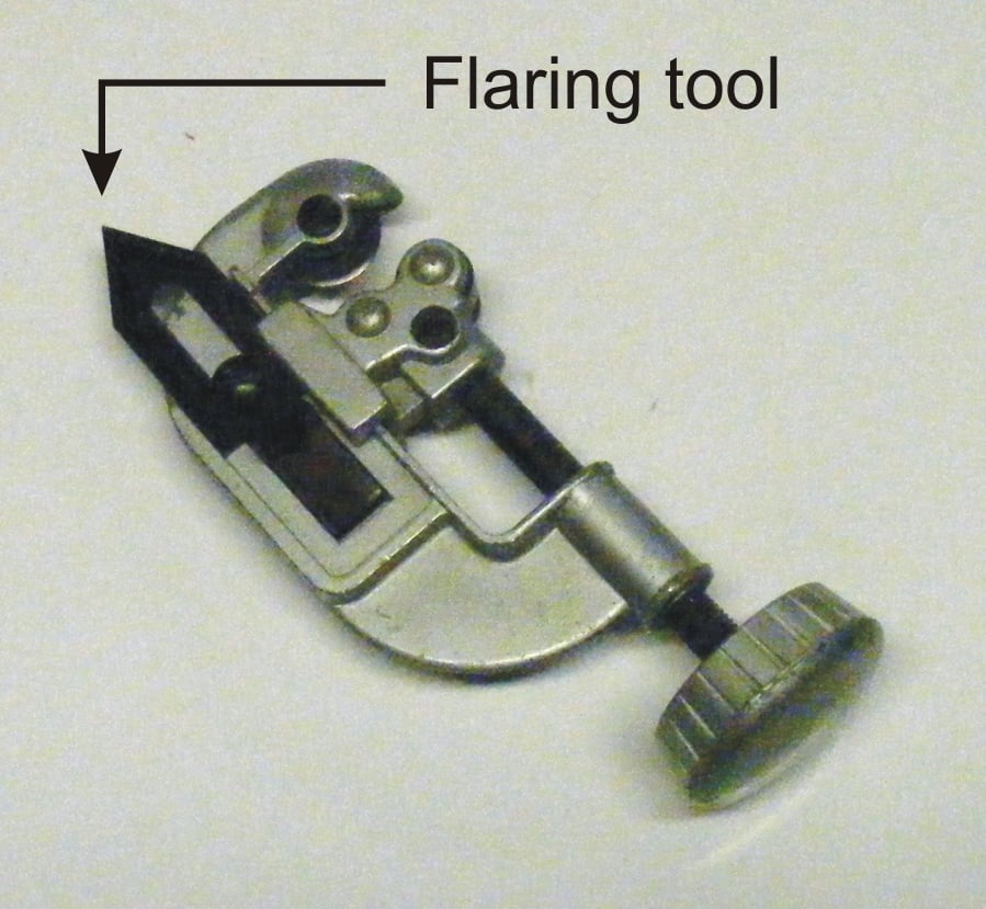
2. If a steel shaft was cut with a tubing cutter, this can cause the shaft to pinch inwards and this is where you want to use the flaring tool inside the butt of the shaft. You may also find the flaring tool useful to remove burrs left inside when cutting the shaft with a motorized tool.
These are a permanent solution
Our counterweights are designed to be more of a permanent solution to counterweighting as opposed to the Tour Lock Pro system which can be readily removed and re-inserted into the butt of the club. The reason they are considered permanent is these are installed prior to the grip. Once gripped, you will not have access or even know a counterweight was installed. So it is important to know how much weight you need ahead of time.
Each 4 grams of weight will reduce the swingweight by one point. For the longer putter weights, it will be slightly more.
| Plug Weight | Swingweight Reduction |
| 8g | 2 |
| 12g | 3 |
| 16g | 4 |
| 20g | 5 |
| 24g | 6 |
| 28g | 7 |
| 32g | 8 |
To epoxy or not to epoxy a counterweight; that is the question
To prevent an unwanted rattle, the counterweights should fit tight inside the shaft. For steel shafts, I would encourage you to use epoxy (fast-setting is fine in this application) to hold them in place. That will ensure no vibration can occur. For graphite shafts, you could do the same, but if you ever wanted to remove the weight at a later date, you might consider an alternative.
Frequently on a graphite shaft, the counterweight will be loose. You can add ordinary masking tape around the stem so it matches the inside diameter of the shaft. This will prevent the counterweight from rattling in the butt as you still have the lip against the butt end and the grip tape and grip to further supporting the counterweight.
Speaking of masking tape, I mentioned before the steel counterweights will not fit a 0.580” steel shaft. You could take the counterweights for graphite shafts and build up the stem with masking or lead tape to match the inner diameter of the steel shaft. See, there is often a simply solution to everything.
Shaft counterweight removal
In the event you want to remove a counterweight, here is the best advice we can give. If you epoxied the counterweight in a steel shaft, simply use a heat gun or torch to break the epoxy bond. Then place the head or lip of the counterweight into your vise and you can twist it out. With graphite shafts I would discourage using any significant heat as it could compromise the integrity of the shaft since they are held together by epoxy resins. This is the reason why I like the masking tape method.
Don’t worry if you see rust
These counterweights are made out of carbon steel and if exposed to humid conditions they can start to create surface rust. Don’t worry as it will have no impact on the usage. Light sandpaper prior to epoxying or adding masking tape is all that is necessary.
